Hierarchical-P coding
Hierarchical-P (hP) coding structure is the hierarchical frame referencing structure that leads to temporal layering of the encoded video stream with only the P-frames. Here’s an example, where every 8th frame is an intra-coded I-frame, and the hierarchical prediction pattern results in 3 temporal layers.
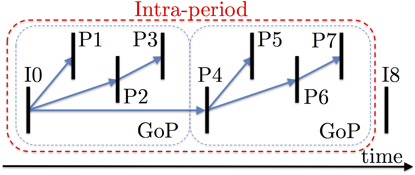
Since no B-frames are used, the decoding order of the frames is the same as their display order. This means that there is no additional delay caused by display-decoding order mismatch. Therefore hP is the de facto temporal layering method for low-delay video call applications. For more information, check out this paper by Hong et al. Despite all the upsides, there is not much online material about the hP structure except for this paper and perhaps a couple of other academic / white papers, let alone an open-source and efficient video encoder that can generate the hP structure.
OK, now the question is: how can we modify a H.264/AVC encoder to produce hP-coded video? In order to find out, we need to understand the reference frame (or picture) management in H.264/AVC standard. I’m sure we’re all painfully aware that reading through any industrial standard is painful, especially the video coding standards. So, here are two awesome books by Iain Richardson to help us understand the concepts in the standard:
There are two key questions we will answer:
- How does the decoder know which decoded picture should be kept around?
- How does it know which frame is to be used as a reference to decode the current frame?
Basics of Reference Picture Management
When a picture is encoded and reconstructed (in the encoder) or decoded (in the decoder), it is placed in the decoded picture buffer and is marked either as
- unused for reference (and hence not used for any further prediction)
- a short-term picture
- a long-term picture.
For a P-slice, the short-term pictures in list0 are sorted in descending PicNum = frame_num % MaxFrameNum by default. For a B-slice, the default order of short-term pictures in list0 (list1) is descending (ascending) POC for earlier (later) pictures, and then ascending (descending) POC for later (earlier) pictures. As each new picture is added to
the short term list at position 0, the indices of the remaining short-term pictures are incremented. If the number
of short-term and long-term pictures is equal to the maximum number of reference frames, the oldest short-term
picture is removed from the buffer, which is known as sliding window memory control. The effect is that the encoder
and decoder each maintain a window of reference pictures. Adaptive memory control commands, that can be sent by the
encoder, manage the short and long-term picture indices. Using these commands, a short-term picture may be assigned
a long-term frame index, or any reference picture may be marked as unused for reference.
The encoder chooses a reference picture from list0 for encoding each MB partition in an inter-coded MB. The choice of the reference picture is signaled by an index number, where index 0 corresponds to the first frame in the short-term section, and the indices of the long-term frames start after the last short-term frame.
In the next post, we’ll examine how these concepts are defined in the H.264/AVC standard.